


















Mathematics, Vol. 12, Pages 1277: Geometric Control and Structure-at-Infinity Control for Disturbance Rejection and Fault Compensation Regarding Buck Converter-Based LED Driver
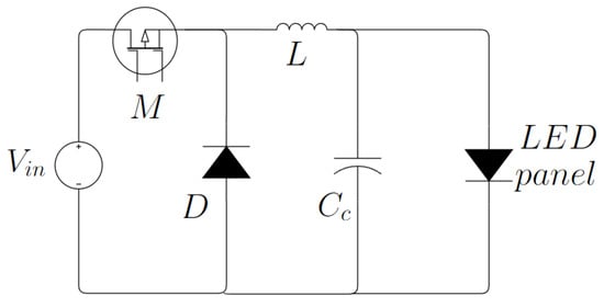
Currently, various light-emitting diode (LED) lighting systems are being developed because LEDs are one of the most used lighting sources for work environments, buildings, homes, and public roads in terms of some of their applications. Similarly, they have low energy consumption, quick responses, and excellent optimal performance in their operation. However, these systems still need to precisely regulate lighting, maintain stable voltage and current in the presence of faults and disturbances, and have a wide range of operations in the event of trajectory changes or monitoring tasks regarding the desired voltage and current. This work presents the design and application of two types of robust controllers (structure-at-infinity control and geometric control) applied to an LED driver using a buck converter. The controllers aim to follow the desired trajectories, attenuate disturbances at the power supply input, and compensate for faults in the actuator (MOSFET) to keep the capacitor voltage and inductor current stable. When comparing the results obtained with the two controllers, it was observed that both present excellent performance in the presence of constant disturbances. However, in scenarios in which variable faults and path changes are implemented, the structure-at-infinity control method shows an overimpulse of output voltage and current ranging from 39 to 42 volts and from 0.3 to 0.45 A, with a margin of error of 1%, and it can generate a failure in the LED driver using a buck converter. On the other hand, when using geometric control, the results are satisfactory, achieving attenuating constant disturbances and variable faults, reaching the desired voltage (40 v to 35 v) and current (0.3 to 0.25 A) with a margin of error of 0.05%, guaranteeing a system without overvoltages or the accelerated degradation of the components due to magnetic conductivity.
Mathematics, Vol. 12, Pages 1277: Geometric Control and Structure-at-Infinity Control for Disturbance Rejection and Fault Compensation Regarding Buck Converter-Based LED Driver
Mathematics doi: 10.3390/math12091277
Authors: Jesse Y. Rumbo-Morales Jair Gómez-Radilla Gerardo Ortiz-Torres Felipe D. J. Sorcia-Vázquez Hector M. Buenabad-Arias Maria A. López-Osorio Carlos A. Torres-Cantero Moises Ramos-Martinez Mario A. Juárez Manuela Calixto-Rodriguez Jorge A. Brizuela-Mendoza Jesús E. Valdez-Resendiz
Currently, various light-emitting diode (LED) lighting systems are being developed because LEDs are one of the most used lighting sources for work environments, buildings, homes, and public roads in terms of some of their applications. Similarly, they have low energy consumption, quick responses, and excellent optimal performance in their operation. However, these systems still need to precisely regulate lighting, maintain stable voltage and current in the presence of faults and disturbances, and have a wide range of operations in the event of trajectory changes or monitoring tasks regarding the desired voltage and current. This work presents the design and application of two types of robust controllers (structure-at-infinity control and geometric control) applied to an LED driver using a buck converter. The controllers aim to follow the desired trajectories, attenuate disturbances at the power supply input, and compensate for faults in the actuator (MOSFET) to keep the capacitor voltage and inductor current stable. When comparing the results obtained with the two controllers, it was observed that both present excellent performance in the presence of constant disturbances. However, in scenarios in which variable faults and path changes are implemented, the structure-at-infinity control method shows an overimpulse of output voltage and current ranging from 39 to 42 volts and from 0.3 to 0.45 A, with a margin of error of 1%, and it can generate a failure in the LED driver using a buck converter. On the other hand, when using geometric control, the results are satisfactory, achieving attenuating constant disturbances and variable faults, reaching the desired voltage (40 v to 35 v) and current (0.3 to 0.25 A) with a margin of error of 0.05%, guaranteeing a system without overvoltages or the accelerated degradation of the components due to magnetic conductivity.
What's Your Reaction?